

اطلاعات پروژه
- دسته : GPON Devices, Huawei OLT 5608T
جزییات پروژه
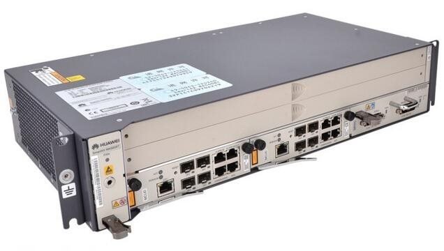
The MA5608T Mini OLT is designed to address Fiber to the premise (FTTP) or deep fiber deployment scenarios where a large OLT chassis may not be the best fit for a variety of reasons Grounding Ground the chassis shell securely so that the influence electricity, leakage electricity can flow to the ground, improving […]
جزئیات بیشتر پروژه
The MA5608T Mini OLT is designed to address Fiber to the premise (FTTP) or deep fiber deployment scenarios where a large OLT chassis may not be the best fit for a variety of reasons
Grounding
Ground the chassis shell securely so that the influence electricity, leakage electricity can flow to the ground, improving the protection against electromagnetic interference.
Use a ground cable to connect the ground point of the chassis shell to the ground bar of the telecommunications room or to the ground directly. It is recommended that the grounding resistance of the telecommunications room should be less than 10 ohms. Refer to the local standards to ground the chassis.
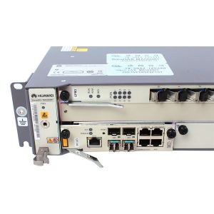
The ground point of the chassis shell is on the left of the chassis, and there is a ground point on the front of the left mounting bracket as shown in.
Grounding of the chassis

Power Distribution Principle
The MA5608T chassis adopts AC and DC power supply. This topic describes the power distribution principle of the MA5608T chassis.
NOTE:
The MA5608T chassis adopts -48 V (-38.4 V to -57.6 V)/-60 V (-38.4 V to -72 V) DC power supply and AC power supply. The following uses the -48 V DC as an example.
Figure 1 Power distribution principle of the MA5608T chassis

The MPWC power interface board leads two -48 V input to the backplane, and then the backplane supplies power to each board.
The MPWC boards supports two -48 V DC input. If one input is off, the other supplies power to the chassis can guarantee normal running of the system.
The MPWD power interface board supports the AC input. After AC/DC conversion, the power is supplied to the system backplane at -48 V DC.
Working Principle
This topic describes the working principle of the MA5608T chassis and the function of each module.
Overview
The MA5608T chassis mainly consists of the service interface module, Ethernet switching module, service control module, narrowband service forwarding unit, and upstream interface module, as shown in Figure 1.
Figure 1 Working principle of the MA5608T chassis

Service Interface Module
The service interface module provides various service ports to access various services.
The P2P interface board supports the P2P FE service.
The GPON service board supports the GPON service.
Others (for example, the Ethernet service access board supports the Ethernet cascading function and Ethernet upstream transmission).
Service Control Module
The service control module of the control board supports the following functions:
Controls the broadband services and manages the device.
Provides the maintenance serial port and network port to facilitate the maintenance personnel to manage the system through the maintenance terminal and the NMS.
Supports the switchover between the active and standby control boards.
Upstream Interface Module
The upstream interface module provides the following upstream ports to transmit services to the upper layer devices.
The GE optical port, which is provided by the GE optical interface board
The 10GE optical port, which is provided by the 10GE uplink interface board
Ventilation
This topic describes the ventilation of the MA5608T chassis.
The MA5608T chassis has a fan tray at the left to blow air for heat dissipation.
The airflow for the MA5608T chassis is as follows: The cool air flows to the chassis through the left side, and then the fans blow the air to the right side of the chassis through the boards. Finally, the air exits through the right side of the chassis.
Figure 1 Ventilation of the MA5608T chassis

Fan Tray
This topic provides the appearance, dimensions, weight, and power consumption of the MA5608T fan tray, and describes the function, configuration, LED, and strategy for fan speed adjustment of the fan tray.

Specification
The functions of the fan tray are as follows:
Heat dissipation
The fan tray is at the left of the service subrack and blows air for heat dissipation of the service subrack. The cool air flows to the subrack from the left of the subrack and then is exhausted from the right of the subrack after passing the boards.
Monitoring
The fan tray is configured with a fan monitoring board. The fan monitoring board transmits speed adjustment signals to the fan tray, collects the rotating speed signals of the fans, and reports the rotating speed signals to the control board.
Speed adjustment
The rotating speed of the fans can be adjusted according to the detected temperature automatically or be adjusted by software manually.
Configuration
The fan tray is configured with 2 fans.
LED
The STATUS LED on the front panel of the fan tray indicates the running status of the fans.
Fans in the fan tray of the MA5608T chassis have the following modes:
Self-check mode: Fans start running at full speed when the device is powered on for the first time or is reset. After fans start up, the duty ratio of fans is initialized.
Troubleshooting mode: Fans run at the old speed and related alarms are reported when faults occur.
Board-based fan speed adjustment mode: According to the temperatures detected by temperature sensors on all boards, fans automatically adjust their speed.
Temperature mode: According to the temperature of the fans, fans automatically adjust their speed.
The status transfer of the fans after the fan tray starts up is shown in Figure 2.
Figure 2 Fan status transfer
